
Google Cloud hub-and-spoke networking: designing it right, and the problems you'll hit
How to design a hub-and-spoke network on Google Cloud with Network Connectivity Center: topology, IP plan, 99.99% hybrid connectivity, DNS, security, and the twelve issues that catch teams out. Editable draw.io HLD and LLDs included.

Every Google Cloud estate starts with one VPC. Then there's a second for the data team, a Shared VPC for prod, a VPN to the office, and somebody peers two networks together "just for now". Two years later nobody can say which network can reach which, and adding a new environment takes a month of change requests.
Hub and spoke fixes that. One place owns the connections to the outside world and the shared services, every environment plugs into it the same way, and the rules about who can talk to whom are written down in the topology instead of in people's heads.
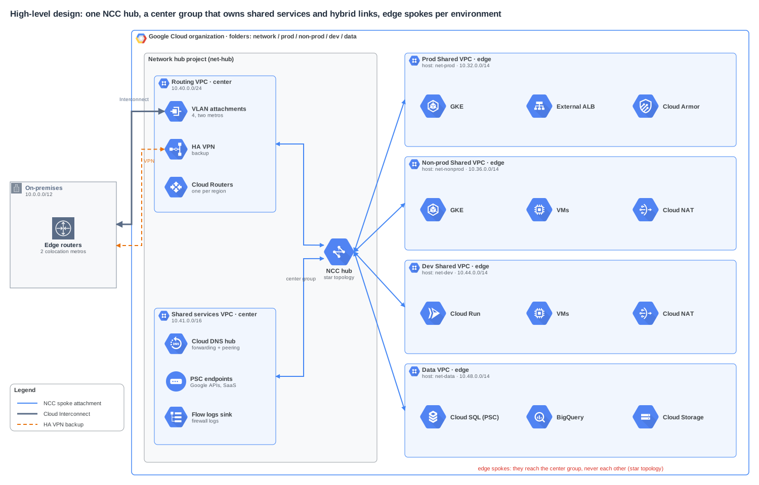
This article is the design I'd hand to a platform team building it today on Google Cloud, using Network Connectivity Center (NCC) as the hub. It has a high-level design and three low-level designs, each one an editable .drawio file built with draw.io's own Google Cloud shapes. You can download them at the end. The second half is the part most guides skip: the problems you will actually run into, and what to do about each.
The short version
- Use NCC as the hub, not a mesh of VPC peerings. Peering isn't transitive and has its own limits. NCC gives you one routing table you can reason about.
- Choose star topology on day one. Prod, non-prod and dev are edge spokes, and they can't reach each other. Shared services and hybrid links sit in the center group. You can't change the topology of a hub after you create it.
- Plan IPs as summaries. One
/14per environment, one/16per region, everything inside a single/11you can advertise to on-premises in one line. - Keep GKE pod ranges out of the routing table. Put them in
100.64.0.0/10and exclude them from export. - Build hybrid for 99.99% from the start. Four VLAN attachments across two metros and two regions, HA VPN as a lower-priority backup.
- Reach other teams' services with Private Service Connect, not routing. It works across edge spokes and across organisations without opening the routing table.
- Centralise DNS, decentralise firewalling. One DNS hub with peering, but firewall policies on every VPC, because NCC moves routes, not permissions.
What NCC actually is
Network Connectivity Center is Google Cloud's managed hub. You create a hub, then attach spokes to it. A spoke can be:
- A VPC spoke: any VPC network, including a Shared VPC host network, and including VPCs in other projects or other organisations (they have to be accepted into the hub, or auto-accepted from projects you list).
- A hybrid spoke: HA VPN tunnels, Interconnect VLAN attachments (including Cross-Cloud Interconnect), or router appliance VMs such as a third-party SD-WAN.
- A producer VPC spoke: the network behind a service that uses private services access, such as some managed databases.
The hub learns each VPC spoke's subnet routes and programs them into every other spoke it's allowed to talk to. Hybrid spokes bring in routes learned over BGP. The result is one routing domain where adding a new environment is "create the VPC, attach it as a spoke", not "add six more peerings".
Mesh or star
When you create the hub you pick a preset topology:
- Mesh (the default): every VPC spoke can reach every other VPC spoke.
- Star: spokes go in a center group or an edge group. Edge spokes can reach the center group and the center group can reach edge spokes, but edge spokes can't reach each other.
For an enterprise, star is almost always right. Prod should not have a route to dev. With mesh, the only thing keeping them apart is a firewall rule somebody might widen one day. With star there is no route at all.
Pick carefully, because the topology can't be changed after the hub is created. Moving from mesh to star later means building a second hub and migrating every spoke.
Design principles
These are the rules the rest of the design follows. Write them down before you build anything, and get them agreed by the people who'll be asked to break them.
- One hub per estate. Not one per environment. A hub per environment puts you right back to stitching hubs together.
- The hub project owns connectivity. A dedicated
net-hubproject holds the routing VPC, the Cloud Routers, the VLAN attachments, the VPN gateways and the shared services VPC. Application teams never get roles in it. - One Shared VPC host per environment.
net-prod,net-nonprod,net-dev,net-data. Service projects attach to the host for their environment, and getroles/compute.networkUseron specific subnets only. - Routes are summarised at every boundary. On-premises learns one prefix for all of Google Cloud. Google Cloud learns one prefix for on-premises.
- Nothing routes between edge spokes. If prod needs something from the data VPC, the data team publishes it with Private Service Connect.
- Every change is code. The hub, spokes, filters and firewall policies live in Terraform. The topology is too important to click together.
Low-level design 1: the IP plan and the Shared VPC
The IP plan is the one thing you can't fix later without moving workloads. Get it right first.
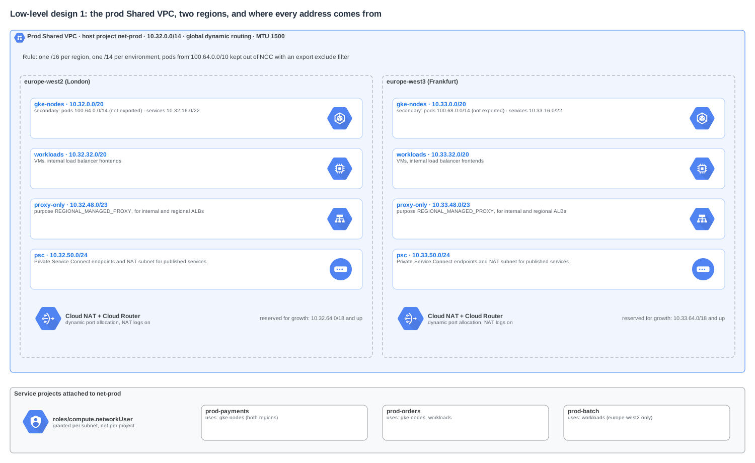
Here is the plan the diagrams use:
| Range | What it is |
|---|---|
10.0.0.0/12 |
On-premises (already in use, not ours to change) |
10.32.0.0/11 |
All of Google Cloud. This is the single prefix on-premises learns. |
10.32.0.0/14 |
Prod Shared VPC (10.32.0.0/16 London, 10.33.0.0/16 Frankfurt) |
10.36.0.0/14 |
Non-prod Shared VPC |
10.40.0.0/24 |
Routing VPC in the hub project |
10.41.0.0/16 |
Shared services VPC in the hub project |
10.44.0.0/14 |
Dev Shared VPC |
10.48.0.0/14 |
Data VPC |
10.52.0.0/14 and up |
Free for the next environment, acquisition or region |
100.64.0.0/10 |
GKE pod ranges, never exported to the hub |
A few choices in there are worth explaining.
Every environment gets a /14 even if it starts tiny. A /14 is four /16s, which is one per region for four regions. Address space inside RFC 1918 feels scarce, but running out inside an environment, and having to bolt on a second range that doesn't summarise, is far worse.
Each region gets the same subnet layout. gke-nodes at .0.0/20, workloads at .32.0/20, the proxy-only subnet at .48.0/23, Private Service Connect at .50.0/24. When someone says "10.33.48.x" you know it's an Envoy proxy for a regional load balancer in Frankfurt, without looking anything up.
GKE pods live in 100.64.0.0/10. A busy GKE cluster can eat a /14 of pod addresses on its own. Putting pods in the shared address space (RFC 6598) keeps them out of the RFC 1918 plan, and an NCC export exclude filter on each VPC spoke keeps them out of the hub. Because they're never exported, every environment can reuse the same pod ranges. Pod traffic leaving the cluster is masqueraded to the node IP, which is in the exported range, so it still reaches on-premises and other spokes.
The VPC MTU is set to 1500, not left at Google's default of 1460. Your VLAN attachments and on-premises network almost certainly run 1500. Matching it avoids a whole class of "small requests work, large ones hang" problems (more on that below). Change MTU before workloads arrive: changing it later means restarting VMs.
Each region has its own Cloud NAT. NAT is regional, and so is Cloud Router. Turn on dynamic port allocation and NAT logging from day one.
Service projects get networkUser per subnet. Granting it at the host project level lets any team put anything in any subnet, including the proxy-only subnet. Per-subnet grants make the subnet layout enforceable.
Low-level design 2: hybrid connectivity and routing
Hybrid connectivity is where availability is won or lost, and where most routing surprises come from.
The routing VPC
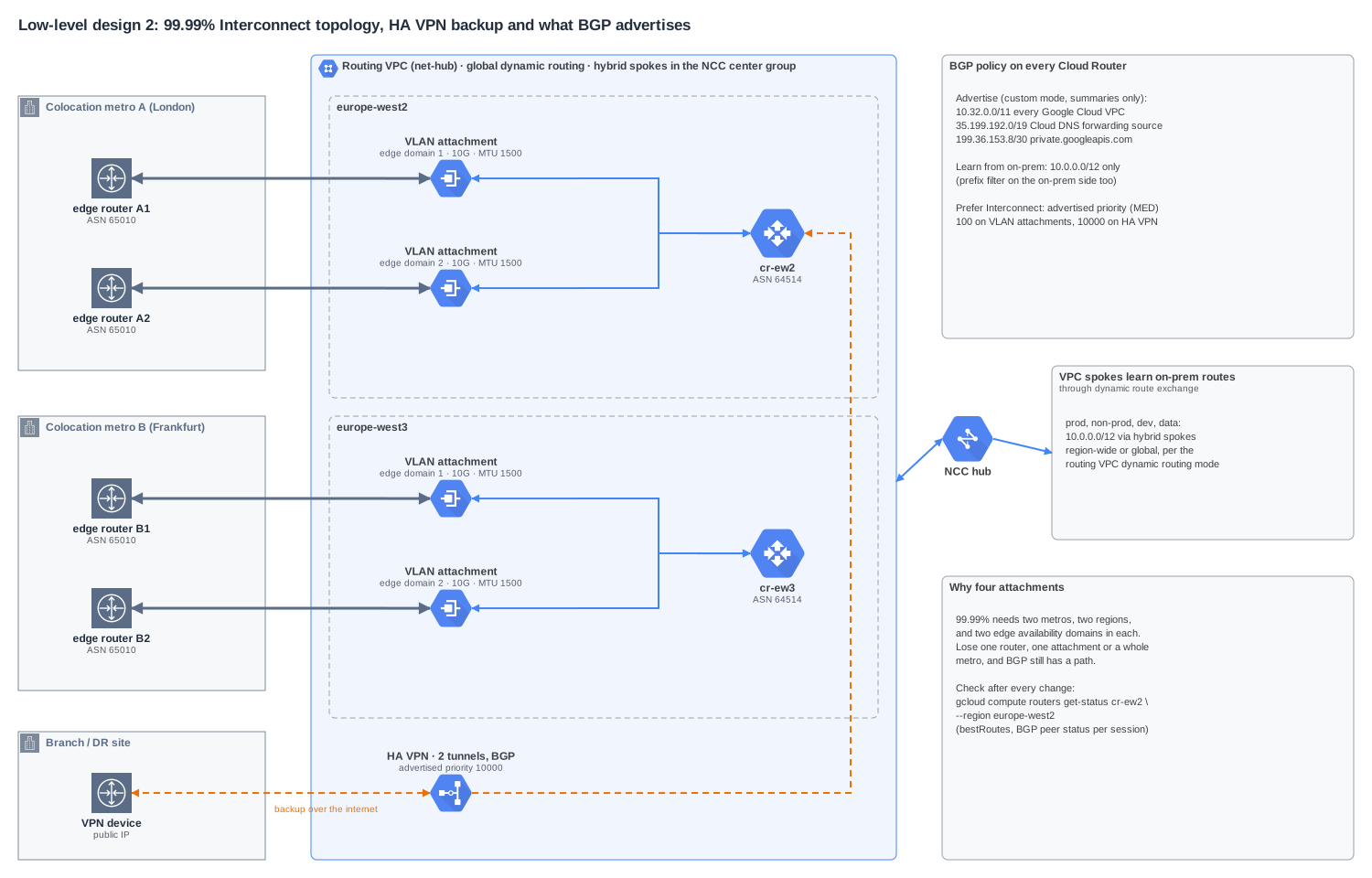
All hybrid connections terminate in one small VPC, the routing VPC, in the hub project. It has almost no workloads, just the Cloud Routers, VLAN attachments and VPN gateways. Each of those connections is attached to NCC as a hybrid spoke in the center group.
Two details matter here:
- The routing VPC must be in the hub project and use global dynamic routing. NCC's dynamic route exchange, which hands BGP-learned routes to VPC spokes, needs the VPC holding the hybrid spokes to be in the same project as the hub. In regional dynamic routing mode, routes learned in London are only programmed in London. With global mode they're programmed in every region.
- In a star topology, site-to-site hybrid spokes have to be in the center group. That's what you want anyway: every edge spoke needs to reach on-premises.
The 99.99% topology
Google's SLA for Dedicated Interconnect depends on the shape you build:
- 99.9%: two VLAN attachments in one metro, in different edge availability domains.
- 99.99%: four VLAN attachments, two in each of two metros, connected to Cloud Routers in two different regions, with global dynamic routing.
For anything you'd call production, build the 99.99% shape from the start. Adding the second metro later means a new colocation contract, a new cross-connect and a routing change, all while people depend on the link. On top of the four attachments, an HA VPN with two tunnels gives you a path that survives even if both colocation providers have a bad day.
What BGP advertises
By default a Cloud Router advertises the subnets of its own VPC, which is the routing VPC, and that's useless to on-premises. Set every Cloud Router to custom advertisement mode and advertise:
10.32.0.0/11: one summary for every Google Cloud VPC.35.199.192.0/19: the range Cloud DNS uses as the source of forwarded queries. Without this, on-premises DNS servers can't send replies back.199.36.153.8/30:private.googleapis.com, so on-premises hosts can reach Google APIs over the Interconnect instead of the internet.
On the receiving side, accept 10.0.0.0/12 and nothing else. Filter it on the on-premises routers too. A default route or a leaked internet table arriving over BGP is the classic way to break a whole estate in one change.
To make the Interconnect the preferred path, use the advertised route priority (sent as the BGP MED): 100 on the VLAN attachment BGP sessions, 10000 on the HA VPN sessions. Do the same in the other direction with your on-premises routing policy, so traffic doesn't go out over the Interconnect and come back over the VPN.
After every change, check what Cloud Router actually learned and chose:
gcloud compute routers get-status cr-ew2 \
  --region europe-west2 \
  --format="yaml(result.bgpPeerStatus,result.bestRoutes)"
How spokes learn on-premises routes
The edge spokes don't have Cloud Routers of their own for hybrid traffic. NCC hands them the routes the routing VPC learned. Each prod VM ends up with a route to 10.0.0.0/12 whose next hop is the hub, and on-premises reaches each spoke through the 10.32.0.0/11 summary.
Low-level design 3: traffic flows and security
A topology diagram tells you what's connected. This one tells you what actually happens to a packet, and what stops the wrong packet.
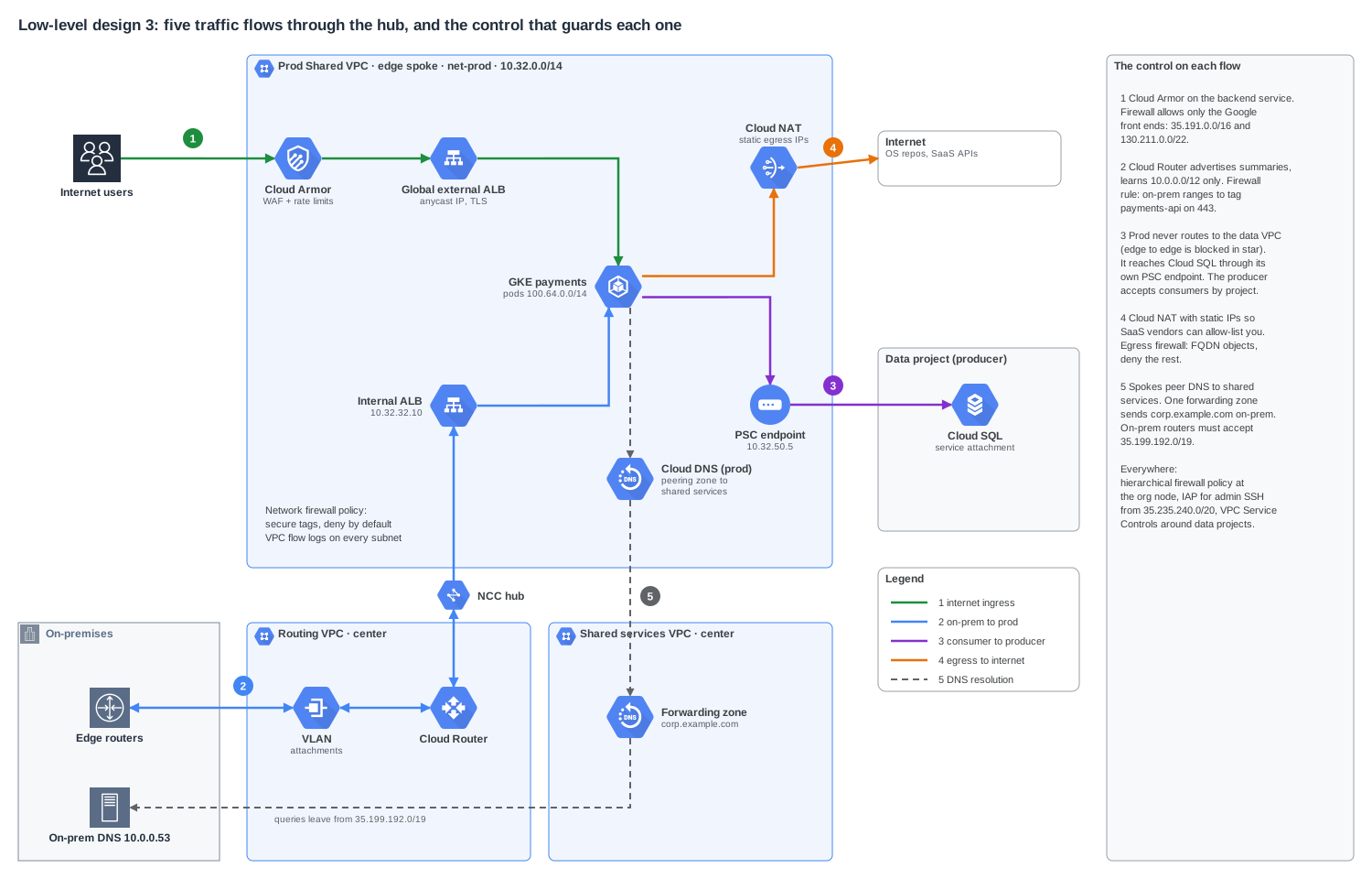
1. Internet to prod. A global external Application Load Balancer with a Cloud Armor policy in front. The backends are in prod, and the firewall allows only Google's front-end and health-check ranges, 35.191.0.0/16 and 130.211.0.0/22, to reach them. Nothing else from the internet gets in.
2. On-premises to prod. BGP over the Interconnect into the routing VPC, through the hub, to an internal load balancer in prod. A firewall rule allows the on-premises range to the workload's secure tag on 443 only. NCC carries the route, but it doesn't carry permission. Each spoke's firewall decides.
3. Prod to the data team's database. This is the flow that surprises people. Prod and data are both edge spokes, so there's no route between them, and that's deliberate. Instead, the data team publishes Cloud SQL (or any internal service) with a Private Service Connect service attachment, and prod creates a PSC endpoint in its own psc subnet. Prod connects to an address in its own VPC. The data team decides which consumer projects to accept. There's no shared routing, no overlap problem, and it works across organisations.
4. Prod to the internet. Cloud NAT with static IPs, so SaaS vendors can allow-list you, and an egress firewall policy that allows named destinations (FQDN objects in Cloud NGFW) and denies everything else.
5. DNS. Each spoke has a DNS peering zone that points at the shared services VPC. The shared services VPC has a forwarding zone that sends corp.example.com to the on-premises resolvers. On-premises in turn forwards gcp.corp.example.com to an inbound server policy in the shared services VPC. One place to change, and every spoke follows.
On top of the per-flow controls, three things apply everywhere:
- A hierarchical firewall policy at the organisation node with the rules nobody should be able to override: allow Identity-Aware Proxy for admin SSH from
35.235.240.0/20, allow health checks, block known-bad ranges, and delegate the rest to network firewall policies withgoto_next. - VPC Service Controls around the data projects, so even a valid credential can't copy data out to a project outside the perimeter.
- VPC flow logs and firewall rule logging, sunk to a central log bucket in the hub project, with sampling turned down on noisy subnets.
The problems you'll actually face
Everything above is the happy path. These are the issues that come up in real estates, roughly in the order teams hit them.
1. Choosing mesh and wanting star later
It's the default, the quickstart uses it, and it works fine for a proof of concept. Six months later security asks why dev can reach prod, and the answer is "because the topology lets it". The topology is fixed at creation, so the fix is a new hub and a migration. Decide on day one.
2. Expecting NCC to carry every route
VPC spokes export their subnet routes. They do not export static routes, dynamic routes learned by their own Cloud Routers, policy-based routes, or the subnet routes of networks peered to them. So:
- A static route in a spoke pointing at a firewall appliance isn't visible anywhere else.
- A database reached through private services access (which is a VPC peering under the hood) isn't reachable from other spokes or from on-premises through the hub.
- A VPN that a team built straight into their own spoke VPC is invisible to everyone else.
The fixes: put every hybrid connection in the routing VPC as a hybrid spoke, prefer Private Service Connect over private services access for managed services, and where you must use private services access, attach the producer network as a producer VPC spoke.
3. Overlapping IP ranges
NCC won't program two overlapping subnet ranges into the same routing table. An acquisition with 10.32.0.0/16, or a team that "just used the default", blocks their spoke from attaching. Export filters can hide the overlapping range, but then nothing can reach it. For the real fix, you either re-IP, or you keep the overlapping network out of the hub and publish its services with PSC, which doesn't care about overlap. Keep a central IPAM, even a spreadsheet with an owner, and make new ranges come from it.
4. GKE eating the address plan
A few large clusters with RFC 1918 pod ranges can consume more space than every VM in the company. Use 100.64.0.0/10 for pods, exclude it from NCC export, and plan for on-premises firewalls to see node IPs, not pod IPs. If a team truly needs on-premises to reach pods directly, that's a sign they need an internal load balancer instead.
5. Hybrid routes missing in some regions
Someone creates the routing VPC with the default regional dynamic routing mode. Routes learned in London are only programmed in London, and the Frankfurt workloads can't reach on-premises until the London VMs fail over. Set the routing VPC (and the spokes) to global dynamic routing, and confirm the hub project and routing VPC project are the same so dynamic route exchange works at all.
6. Asymmetric routing and the wrong path winning
Traffic leaves over the Interconnect and the reply comes back over the VPN. A stateful firewall on-premises sees half a conversation and drops it. Or the VPN backup quietly becomes the primary path because it advertises a more specific prefix. Hybrid spokes in NCC use the standard best-path selection, so make the preference explicit in both directions: advertised priority on Cloud Router, local preference on-premises, and the same prefix lengths on every path.
7. MTU mismatches
Google Cloud VPCs default to 1460 bytes. VLAN attachments support 1440, 1500 and 8896, and on-premises usually runs 1500. HA VPN takes another chunk for IPsec headers. If path MTU discovery is blocked anywhere (a firewall dropping ICMP is enough), small requests work and large ones hang: SSH connects but scp stalls, health checks pass but uploads fail. Pick one MTU per path, set it on the VPCs and attachments, and allow ICMP "fragmentation needed" through every firewall.
8. DNS that works from one place only
The common failures:
- On-premises resolvers never reply because
35.199.192.0/19isn't advertised to them, or their firewall drops it. - A team adds a private zone directly in their spoke, and now that name resolves differently there than anywhere else.
- Someone tries to chain DNS peering through two hops. DNS peering isn't transitive, so a spoke peering to a VPC that itself only peers onwards gets nothing.
Keep every forwarding zone in the shared services VPC, give spokes peering zones only, and add a policy check that rejects private zones in spoke projects.
9. Thinking the hub is a firewall
NCC decides what's routable. It doesn't decide what's allowed. Every VPC still starts from the implied rules (deny ingress, allow egress), and every new spoke needs its firewall policy in place before workloads land. If you need inspection between the center group and edge spokes, plan for it explicitly: NCC supports a hybrid inspection preset and NCC Gateway for security service edge inspection, and you choose that when you design the hub, not after.
10. Quotas and limits
The numbers are generous but they're real. A hub supports up to 250 active VPC spokes. A hybrid spoke holds up to 8 VPN tunnels, 6 VLAN attachments or 8 router appliance instances. Each VPC spoke can have 16 export filter ranges and each hybrid spoke 32. Cloud Router has its own limits on learned routes per region. The one that bites most is the route count when on-premises advertises hundreds of small prefixes. Summarise on-premises too, and check the NCC quotas page before onboarding a big batch of spokes.
11. Things NCC doesn't support
Legacy networks can't be spokes. Classic VPN can't be a hybrid spoke, only HA VPN. BGP communities aren't supported, so any on-premises routing policy that depends on tagging routes with communities has to use prefixes and MED instead. IPv6 support for hybrid spokes is still in preview at the time of writing. Find these out in design review, not in the migration window.
12. Cloud NAT port exhaustion
A pod that opens thousands of connections to one SaaS endpoint can run out of NAT source ports, and the symptom is random connection timeouts that nobody can reproduce. Use dynamic port allocation, set a sensible maximum ports per VM, and alert on the nat/dropped_sent_packets_count metric with reason OUT_OF_RESOURCES.
Pre-flight checklist
Before the first production spoke goes live:
- Hub created with star topology, in a dedicated hub project
- Routing VPC in the hub project, global dynamic routing, MTU agreed
- IP plan published with an owner, with one summary for all of Google Cloud
- Pod ranges in
100.64.0.0/10and excluded from export on every VPC spoke - Four VLAN attachments in two metros and two regions, plus HA VPN backup
- Custom Cloud Router advertisements, inbound prefix filters, MED set
- Failover tested on purpose: drop one attachment, then one metro, then the Interconnect entirely
- DNS forwarding in both directions,
35.199.192.0/19reachable from on-premises - Hierarchical firewall policy at the org, network firewall policy on every spoke
- PSC used for cross-environment services, never edge-to-edge routing
- Flow logs, firewall logs and NAT logs flowing to the central bucket
- Everything above in Terraform, with the topology reviewed in pull requests
Download the diagrams
All four diagrams are editable draw.io files using the Google Cloud shapes that ship with draw.io. Open them in diagrams.net or the draw.io desktop app and change the CIDRs, regions and names to match your estate.
- All four diagrams in one file (4 pages)
- High-level design
- LLD 1: subnets and IP plan
- LLD 2: hybrid connectivity and routing
- LLD 3: traffic flows and security
The CIDRs, ASNs and addresses are examples. Check current quotas, SLAs and prices for your own regions before you order anything.
References
- Network Connectivity Center overview
- NCC connectivity topologies (mesh, star, hybrid inspection)
- NCC dynamic route exchange with VPC spokes
- NCC quotas and limits
- Dedicated Interconnect: 99.99% availability topology
- Cloud Router: custom route advertisements
- Cloud DNS forwarding zones
- Private Service Connect overview
- Shared VPC overview
- VPC maximum transmission unit
- Hierarchical firewall policies
- Cloud NAT: port allocation